


An Article by Paul Ellis
Change is a constant, both in life and over the production span of a locomotive. Subtle, or very obvious, changes may appear over a model’s production, aside from railroad options, based upon feedback from the railroads, changes to vendor-supplied components, or to make production simpler and/or cheaper.
Locomotives produced by GM’s Electro-Motive Division (EMD) are well known for this, leading to the compilation of these differences as “Phases” by locomotive enthusiasts and modelers. While not officially recognized by the builders, production phases can be a useful tool for modelers and railfans to differentiate physical differences over the production span of a locomotive model, with the GP40, in particular, highlighting numerous changes over its production life.
Care must be taken when using phases as spotting features however, since some of these differences may overlap depending upon when the locomotive was built or changed altogether as a result of wreck repairs, rebuilding programs, or even routine maintenance that could have simple components like sub-base doors being swapped around. There is a lot to look out for, and as the joke among railfans and prototype modelers goes, EMD stands for “Every Model Different”, owing to the myriad changes evident during a typical production run. The following EMD GP40 production phase breakdown referred to by many prototype modelers was originally compiled by enthusiast James D. Thompson, and can be found online here.
Phase Ia1
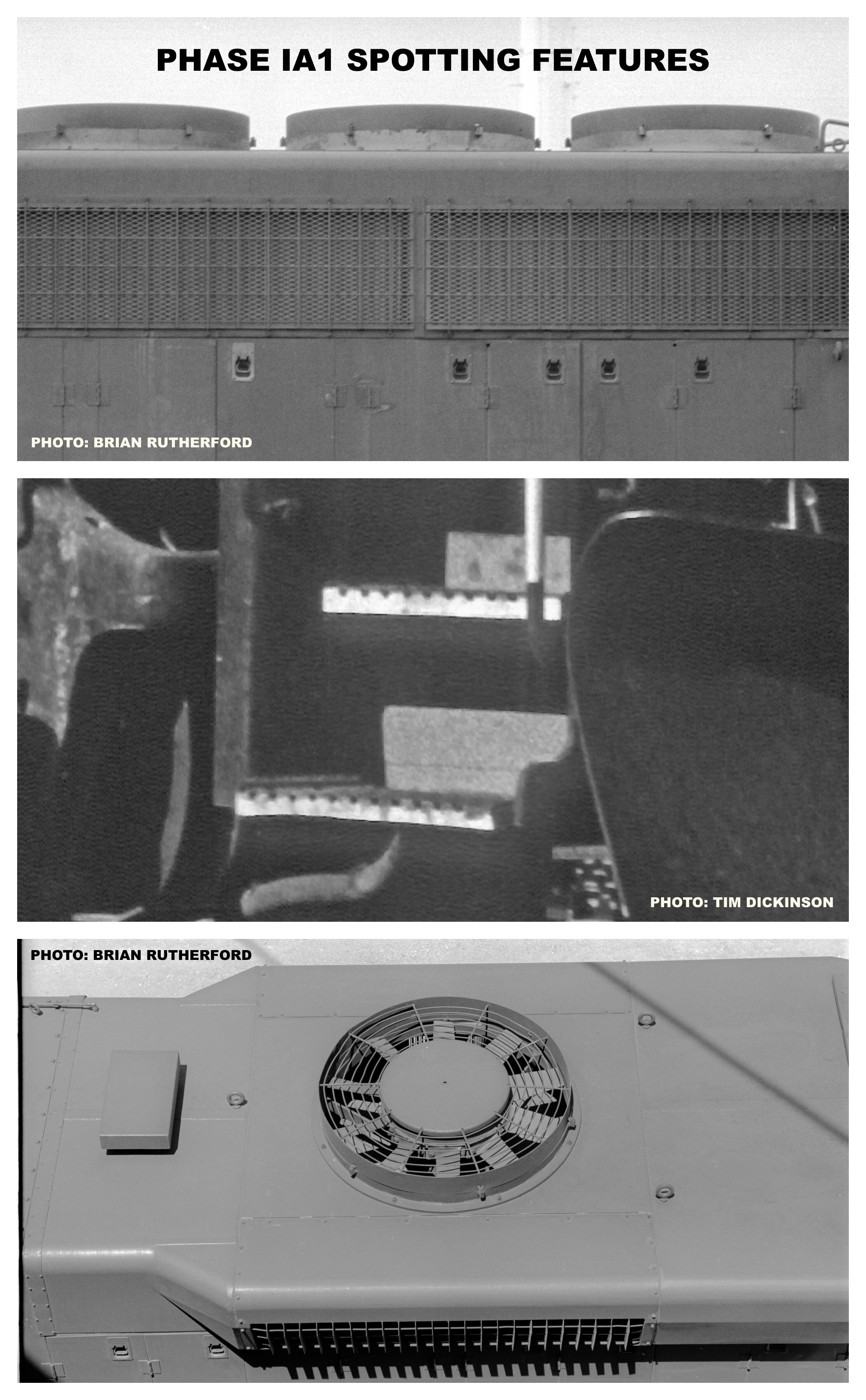
The initial production phase was distinguished by “chickenwire” (diamond-pattern) sub-mesh under the main radiator intake grills. This style would last through Phase IIa3 production. The end pilot plates featured small “nubs” at their bottoms, similar to those on the predecessor GP35, helping to protect the bottom steps where they protruded past the vertical pilot face. Note that this feature could change visually, depending upon the overall stepwell height optioned by the railroad. Roads that optioned lower bottom steps would feature a “tall” nub at each corner. The radiator and dynamic brake fans featured a spiral-pattern grill with a large center “pan” over the fan hub. The single drainage hole for the inertial filtration compartment on the left side of the hood immediately behind the cab was located close to the walkway, and on the fireman’s side, the bottom-most hole of the two holes on that side was in a similar location, a few inches from the walkway deck. Lastly, the large “sub-base” air brake equipment doors directly underneath the cab, on both sides, were smooth.
Phase Ia2
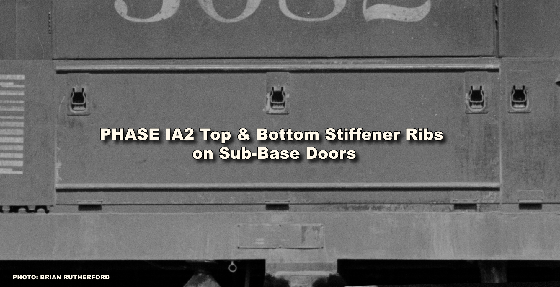
While identical overall to Phase Ia1 production, Phase Ia2 production introduced top and bottom stiffener ribs on the left (fireman’s) side sub-base equipment door underneath the cab. These ribs were notable in being “terminating” style ribs that stopped just short of the end of the door.
Phase Ia3
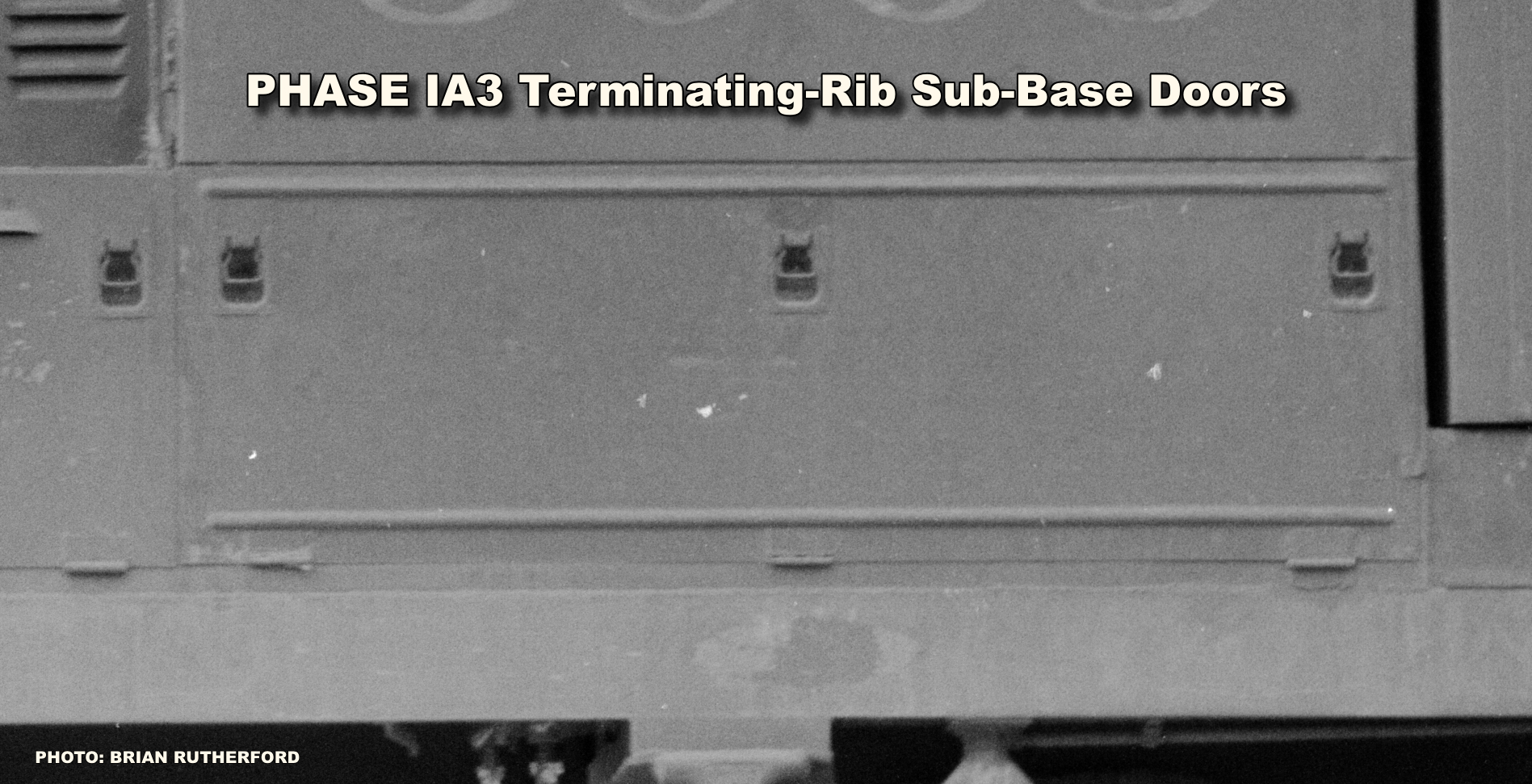
A progression of Phase Ia2, Phase Ia3 production featured terminating-rib sub-base equipment doors on both sides—otherwise, no other discernible changes from the prior two phases.
Phase Ia4
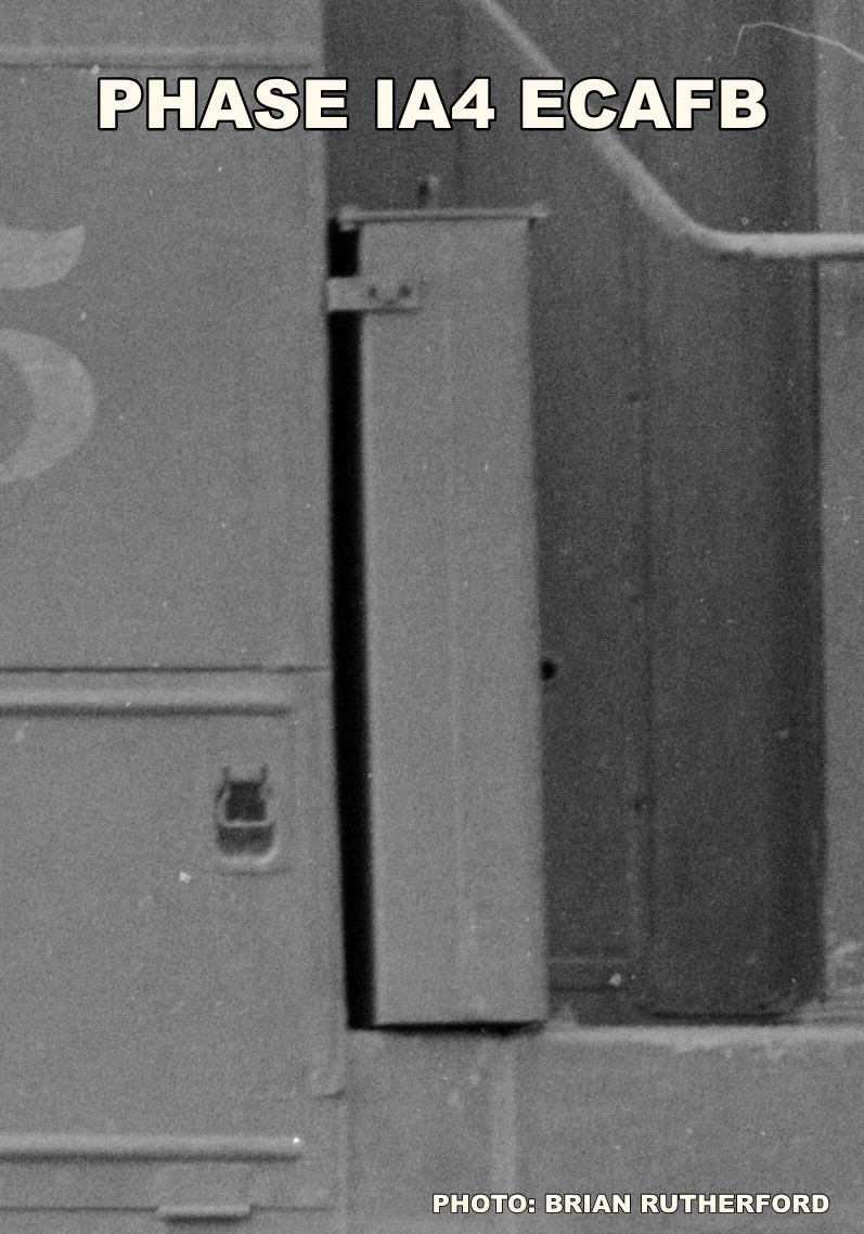
This production phase introduced an ECAFB (Electrical Cabinet Air Filter Box) behind the cab, left hand side, on some production. This early “skinny” air filter housing foreshadowed the wider housings that would become standard on Dash-2 production in 1972.
Phase IIa1
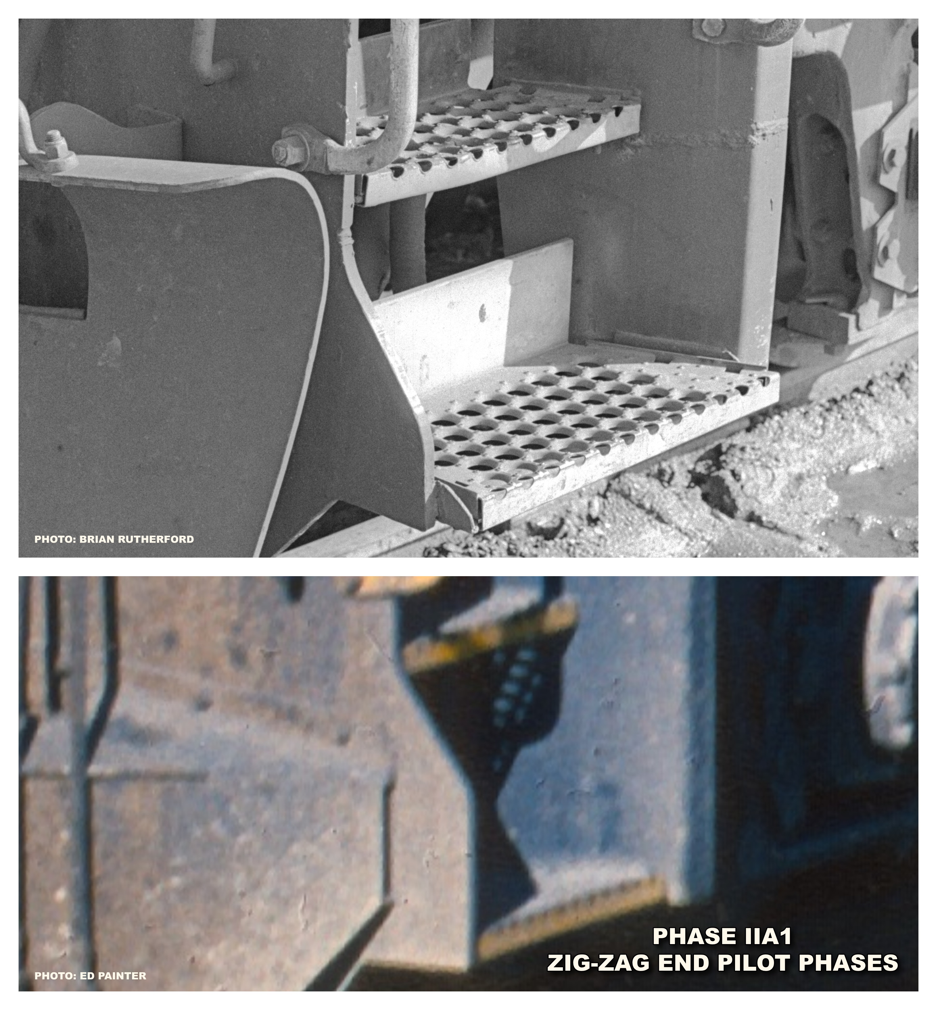
This phase highlighted a significant external change to GP40 production, in the form of “zig-zag” end pilot plates. Instead of the squarish “nub” at the location of the bottom corner steps, the profile changed to a double taper. As with earlier production, the overall step placement optioned by the railroad would have an impact on outward appearance (“tall” or “short” zig-zag).
Phase IIa2
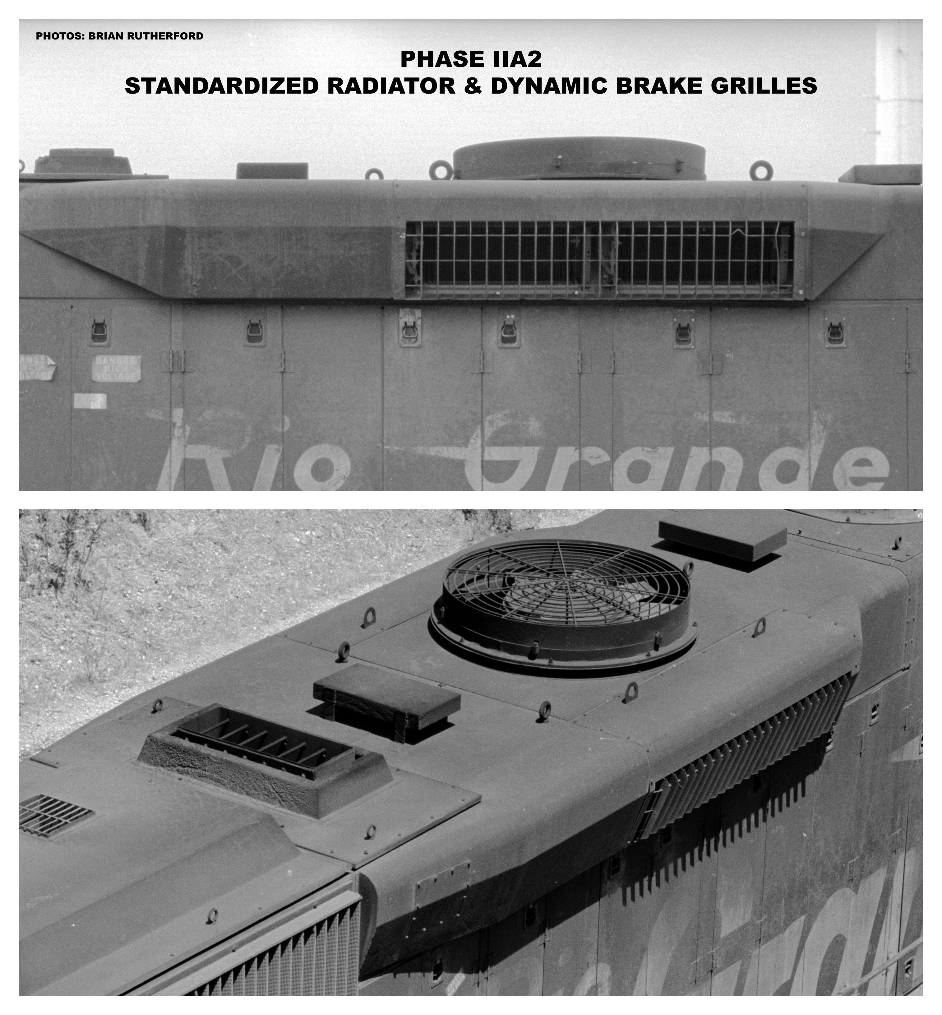
The ECAFB would become a standard on all production of this and later phases and was also made available as an item that owners of earlier production could retrofit to their GP40s. Up top, the radiator and dynamic brake fan housing grills saw the elimination of the center “pan”, and the grill ring changing from a spiral design, to separate, concentric rings welded to the grill radial arms.
Phase IIa3
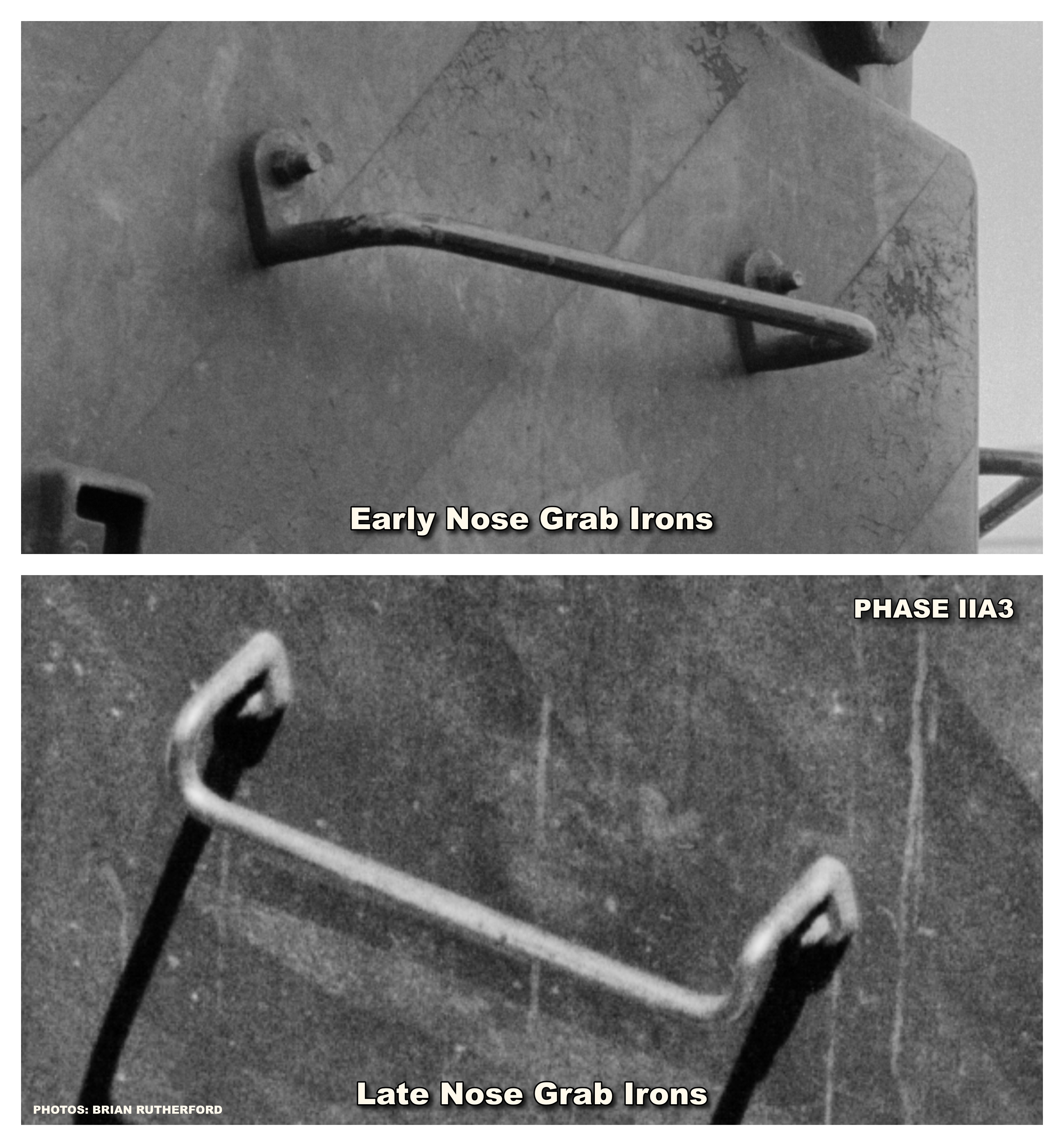
The introduction of this phase saw the grabs on the front and top of the low nose change from a “straight” style, to “drop” style grabs, with the mounting assemblies on them changing from the top end of each grab iron, to the bottom (drop) end. Production part way through this phase also saw the stiffener ribs on the cab sub-base equipment doors change to “non-terminating” style ribs that continued to the end of each door.
Phase IIb
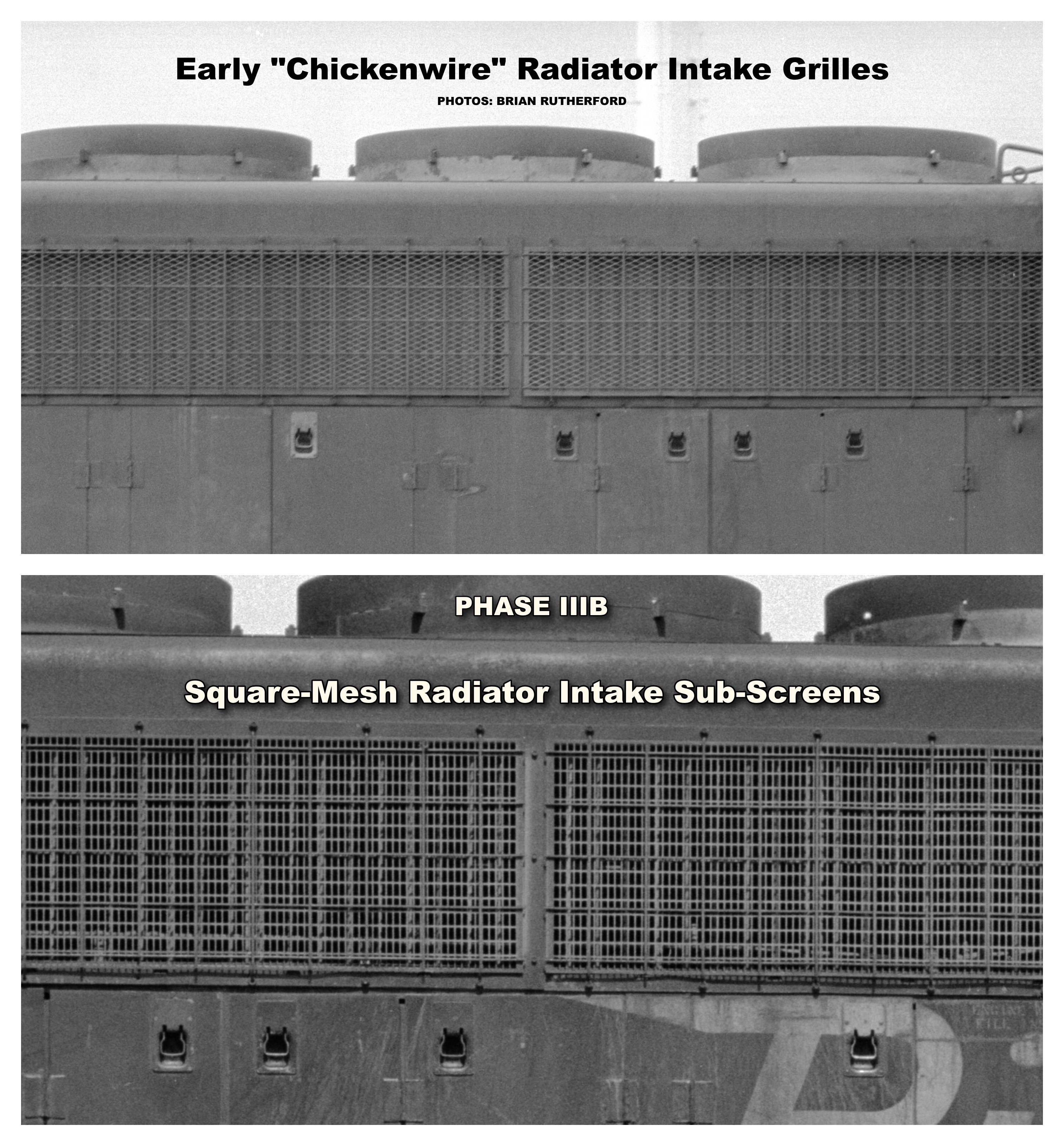
This phase saw the first appearance of square-mesh radiator intake sub-screens, replacing the diamond-mesh “chicken-wire” design of prior production.
Phase IIc
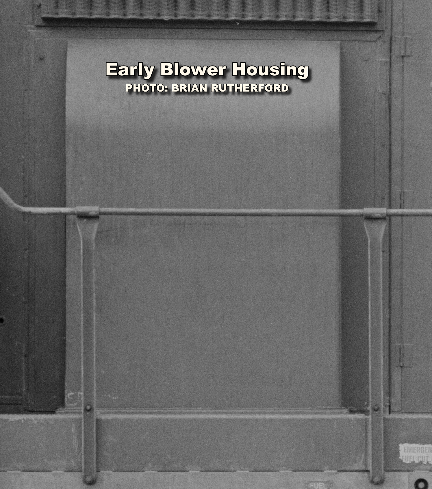
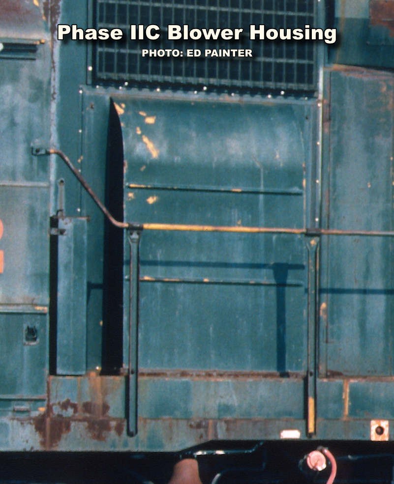
Some of the most noticeable production changes were evident on this phase, where the traction motor blower housing gained a pair of stiffener ribs, making it appear similar to the housing used on most domestic Dash-2 production. The handrail stanchions would also be revised; those on the ends changed to a “deck-mount” style, as opposed to the mixed deck and end mount arrangement of earlier production. The side-long handrail stanchion placement would also change, from the staggered placement of earlier units to uniform 4-foot centers. Also, as a result of lessons learned from operating experience, the dynamic brake housing (on units optioned with that feature) would feature longer tapers on their front end, to give the electrical cables for the dynamics some extra space away from the hot turbocharger exhaust and possible damage.
Phase IIIc
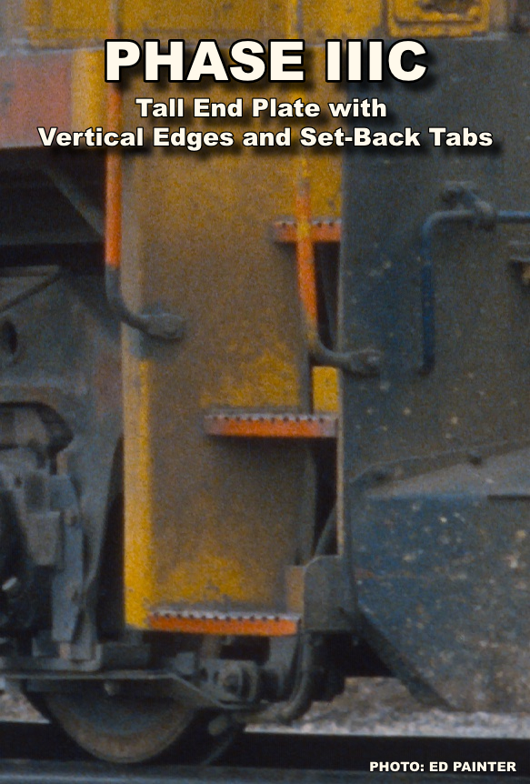
This final production variant introduced a new style of pilot end plate, which had vertical edges, and tall, set-back tabs protecting the bottom steps, a design which would carry over to Dash-2 production.


